


Dynamic Host Configuration Protocol or DHCP is a networking protocol that allows for the automatic assignment of IP addresses to devices in a network. You have probably seen DHCP in action at the most basic level when you connect your laptop to an ISP router (like MTN-HynetFlex) or your phone's hotspot. Every new device that joins the Wifi network will get a local IP address, usually in the range 192.168.0.* or 172.16.*.* where * is a number between 0 and 255.
This automatic assignment of IP addresses isn't limited to Wifi networks. It extends to ISP Cell Towers, Satellite internet like Starlink, and cable internet like Fibreone. Without DHCP, these massive networks will require physical agents in call centers to manage who gets what IP address. While this is not only a hassle, it will be a huge cost to the service provider.
One easy way to practice a DHCP setup is in a local network simulation environment like Cisco Packet Tracer. This article will teach you how to configure DHCP on a router for a simple two-computer, two-switch network. The router will assign the IP addresses to the computers in each network so that inter-network communication can happen.
Prerequisites
The Cisco Packet Tracer tool is the only thing you need to follow along. Download it for your operating system here.
Setting up the lab environment
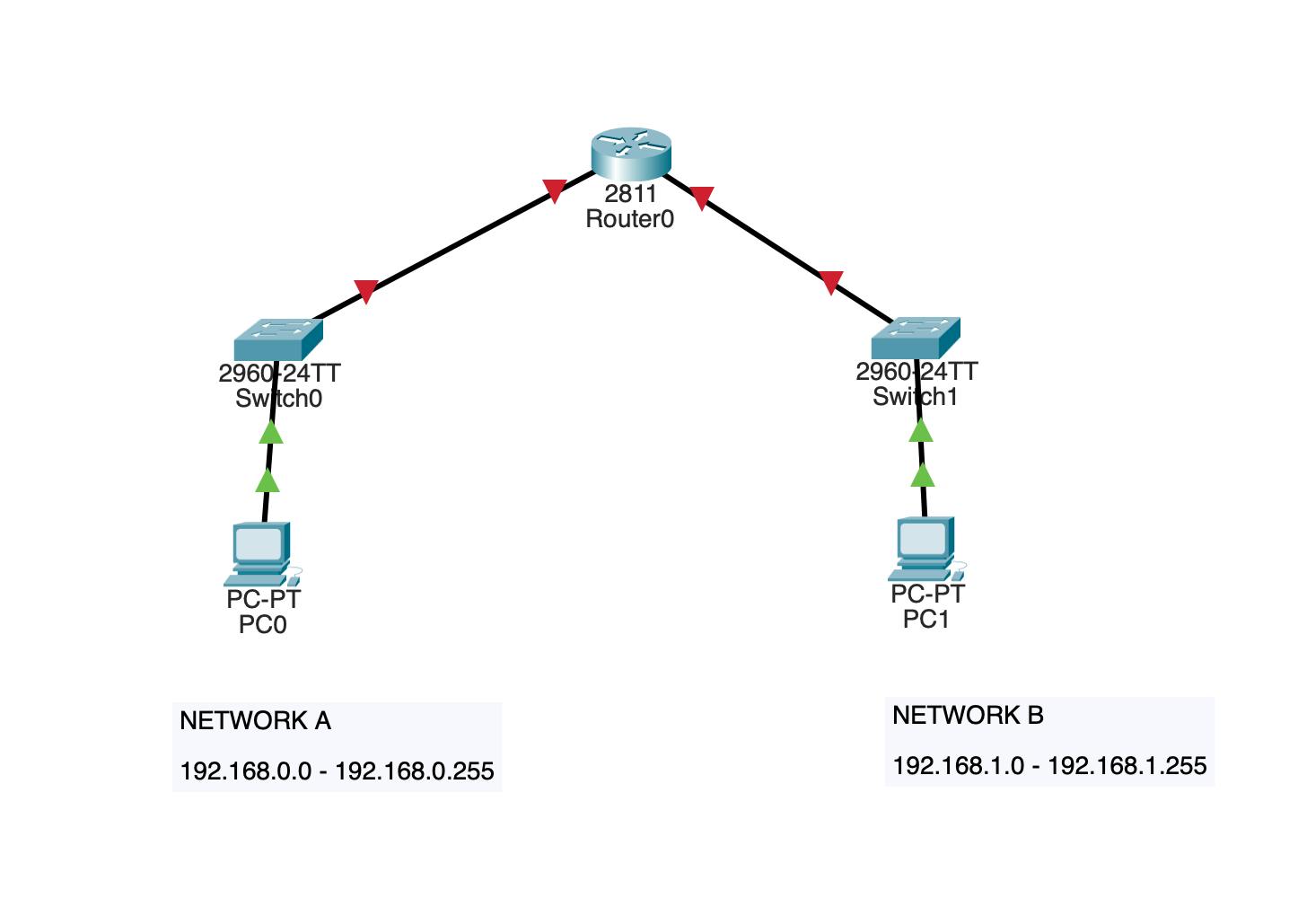
The goal of this lab is to connect two networks with a router that will automatically assign IP addresses to the devices in both networks. To make referencing easier, the networks are labeled Network A and Network B. Both have a router and a single PC. You can see the network topology in the diagram below:
You can also download this lab's setup file if you're in haste.
Configuring DHCP on the Router
You will use the Router's CLI to configure DHCP. The commands to perform this configuration are as follows:
enable
config t
hostname dhcp-router

int f0/0
ip address 192.168.0.1 255.255.255.0
no shutdown
!

int f0/1
ip address 192.168.1.1 255.255.255.0
no shutdown
!

ip dhcp excluded-address 192.168.0.1
ip dhcp excluded-address 192.168.1.1

ip dhcp pool 192.168.0.1
network 192.168.0.0 255.255.255.0
default-router 192.168.0.1
dns-server 8.8.8.8


ip dhcp pool 192.168.1.1
network 192.168.1.0 255.255.255.0
default-router 192.168.1.1
dns-server 8.8.8.8
The major commands here are the commands that set the interface IP address and turn it on, i.e.
int f0/0
ip address 192.168.0.1 255.255.255.0
no shutdown
Then the excluded address commands exclude the gateway IP address from being assigned to newly connected devices. The first usable address in the network is chosen as the Gateway address, following the normal convention.
ip dhcp excluded-address 192.168.0.1
ip dhcp excluded-address 192.168.1.1
Finally, the ip dhcp pool command creates a DHCP pool with a given network range and a default router. The default router's IP address is the same as the gateway address, which in essence is the address of the interface where the switch connects to the router. For Network A, this interface is to the left with an address of 192.168.0.1, and for Network B to the right, it has an address of 192.168.1.1.
ip dhcp pool 192.168.0.1
network 192.168.0.0 255.255.255.0
default-router 192.168.0.1
dns-server 8.8.8.8
You can copy the initial code block and paste it into the router CLI. You first have to click on the router, and then navigate to the CLI tab. If you see the prompt asking you if you would like to enter the initial configuration dialog, input "no" and press the enter or return key. Afterward, you should go ahead to paste the configuration. This process is shown in the GIF below:

The configuration turns on the Router's interfaces and sets the DHCP pool for both networks. The next step is to enter each connected device's IP configuration menu to request an IP address in the DHCP mode. This IP address request takes approximately 5 seconds. On success, the target device will have an IP address, subnet mask, default gateway, and DNS server set up. The process for DHCP IP request is shown in the GIF below:

With your configuration set and IP addresses configured, the final step is to test inter-network communication between the two devices. There are two ways of doing this. The first is to enter the command prompt desktop app of the PC in Network A and ping the PC on Network B. During this ping operation, the first packet will be lost because the communication channel is yet to be initialized. The other pings will succeed. The second method on the other hand involves using the packet messaging option to send a message from one of the PC to the other. The status of the sent message will be shown at the bottom of the application. This process is shown in the GIF below:
Conclusion
This article showed you how to configure DHCP at the router level in a network. You set up the network devices, connected them using straight-through ethernet cables, and finally, you used the Router's CLI to input configuration commands that set the DHCP pools for both networks.
Without DHCP, you would have to manually assign IP addresses to new devices that are joining a network, and free up these addresses when a device leaves the network. For very simple networks, you might not need DHCP because you can easily manage the IP addresses yourself, but for more involved networks, involving more than 10 devices, it becomes a hassle to manage devices and it's often better to resort to DHCP.