


Networks are all around us, from the simple hotspot-wifi configuration that you use to connect your laptop to the internet, to your school or office wifi, they are everywhere. Don't believe me? Think about your local church or mosque. How do the microphones work wirelessly? Networks!
Say you just got hired by a mid-size manufacturing company, and the newly formed social media marketing department needs their work PCs interconnected for easy sharing of files. They also want to be able to communicate with the sales team. Your task is to interconnect these departments for easy communication.
Scope of the task at hand
The company has a general IP address space of 216.21.5.*, ranging from 0 to 255. This means that every possible IP address that could be assigned to a device (be it a laptop, PC, smartphone, or printer), will start with 216.21.5.. So a printer could be assigned an address of 216.21.5.40 while the manager's laptop is assigned 216.21.5.56. To ensure that confidentiality is maintained within the company, such that intra-network communication is limited at the department level and that inter-network communication only happens over a router, the network administrator can utilize subnetting.
Subnetting is a network segmentation technique that works by diving the overall network into equal parts know as subnets. Each subnet has a defined address range, and sees other subnets as a different network. So devices in the marketing department subnet can only share information with other devices in the marketing department. If a device in the marketing subnet want to share information with a device in the sales subnet, it must go through a router. The network administrator (you) can configure the router to allow only certain types data through from the sales to marketing subnet.
The network administrator (still you) can also configure the router to prevent say the sales and marketing departments from access sensitive information that reside on a database in the admin subnet. So only admins will be able to access this admin subnet based on routing rules.
The company utilizes a subnet mask of 255.255.255.224 or /27 to break up their network into 32-address sections with a total of 8 sections (32 x 8 = 256 total addresses). With 8 subnets, the company can have 8 different departments, with each department connected to other departments over a router. The process of subnet masking can be explored with this IP Subnet Calculator tool. The image below shows a visual representation of the problem on the Cisco Packet Tracer tool. Cisco Packet Tracer is a network simulation tool for designing and debugging networks.

The diagram above shows the sales and marketing departments. The sales department has three PCs interconnected in the same subnet with a subnet range of 216.21.5.0 to 216.21.5.31 (the first subnet range). You can see all the subnet ranges for the IP address space of 216.21.5.0 to 216.21.5.255 utilizing the subnet mask 255.255.255.224 in the table below:
| S/N | Start Range | End Range | |
| 1 | 216.21.5.0 | 216.21.5.31 | |
| 2 | 216.21.5.32 | 216.21.5.63 | |
| 3 | 216.21.5.64 | 216.21.5.95 | |
| 4 | 216.21.5.96 | 216.21.5.127 | |
| 5 | 216.21.5.128 | 216.21.5.159 | |
| 6 | 216.21.5.160 | 216.21.5.191 | |
| 7 | 216.21.5.192 | 216.21.5.223 | |
| 8 | 216.21.5.224 | 216.21.5.255 |
The first subnet's first and last addresses are the network and broadcast addresses and so cannot be assigned as a host or gateway address. The three PCs in the sales department are assigned addresses within this range (216.21.5.0 - 216.21.31) and since they have the same subnet mask, they will be able to communicate over the Switch. The diagram below shows the IP address, subnet mask, and default gateway of the first PC in the sales department's subnet.

The task at hand is to connect the sales to the marketing department. But before doing that, you can interconnect the PCs in the marketing department using a switch so that inter-network communication can take place. To do this, you can connect the FastEthernet0 interface of the first PC to the FastEthernet0/1 of the Switch and then connect the FastEthernet0 interface of the second PC to the FastEthernet0/2 of the Switch. The Switch allows for the interconnection of up to 24 PCs through the FastEthernet interface.

After a successful connection of the two PCs, the next step is to pick a subnet where the two PCs will reside, and then assign an IP address to each of them.
Assigning IP Addresses to PCs in a Subnet
Refrencing the Subnet table from the previous section, you as the Network Administrator can pick a free subnet for the marketing department. Say the company has used the first three subnets for other departments (sales included), you can then pick the fourth subnet (216.21.5.96 - 216.21.5.127) for the marketing department. With the range chosen, you can assign the last usable IP address, i.e. 216.21.5.126, as the default gateway of the marketing subnet.
The image below shows the IP configuration of the first PC in the marketing department (PC4). Note that the subnet mask defaults to 255.255.255.224 and that the default gateway is set.
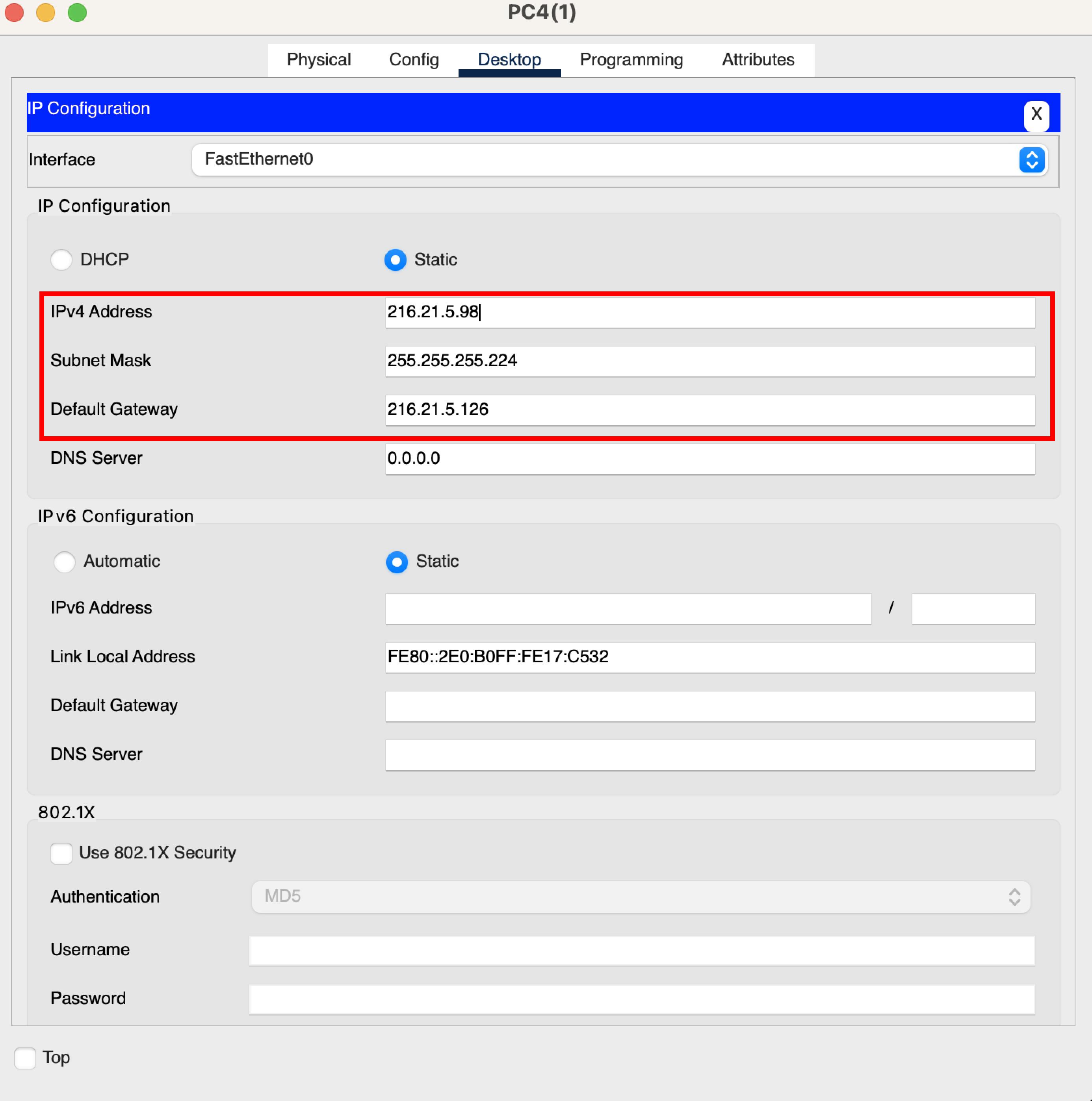
Then the image below shows that for the second PC in the marketing department (PC3).

Now that the IP addresses have been assigned, you can test the communication of these two PCs.
Connecting the two networks using a Router
A router is a networking device that serves to connect two or more different networks. The sales and marketing subnets discussed so far are two separate networks that require a router in order for communication to take place. You can use a simple Cisco 1941 router within the Cisco Packet Tracer tool to connect these networks.
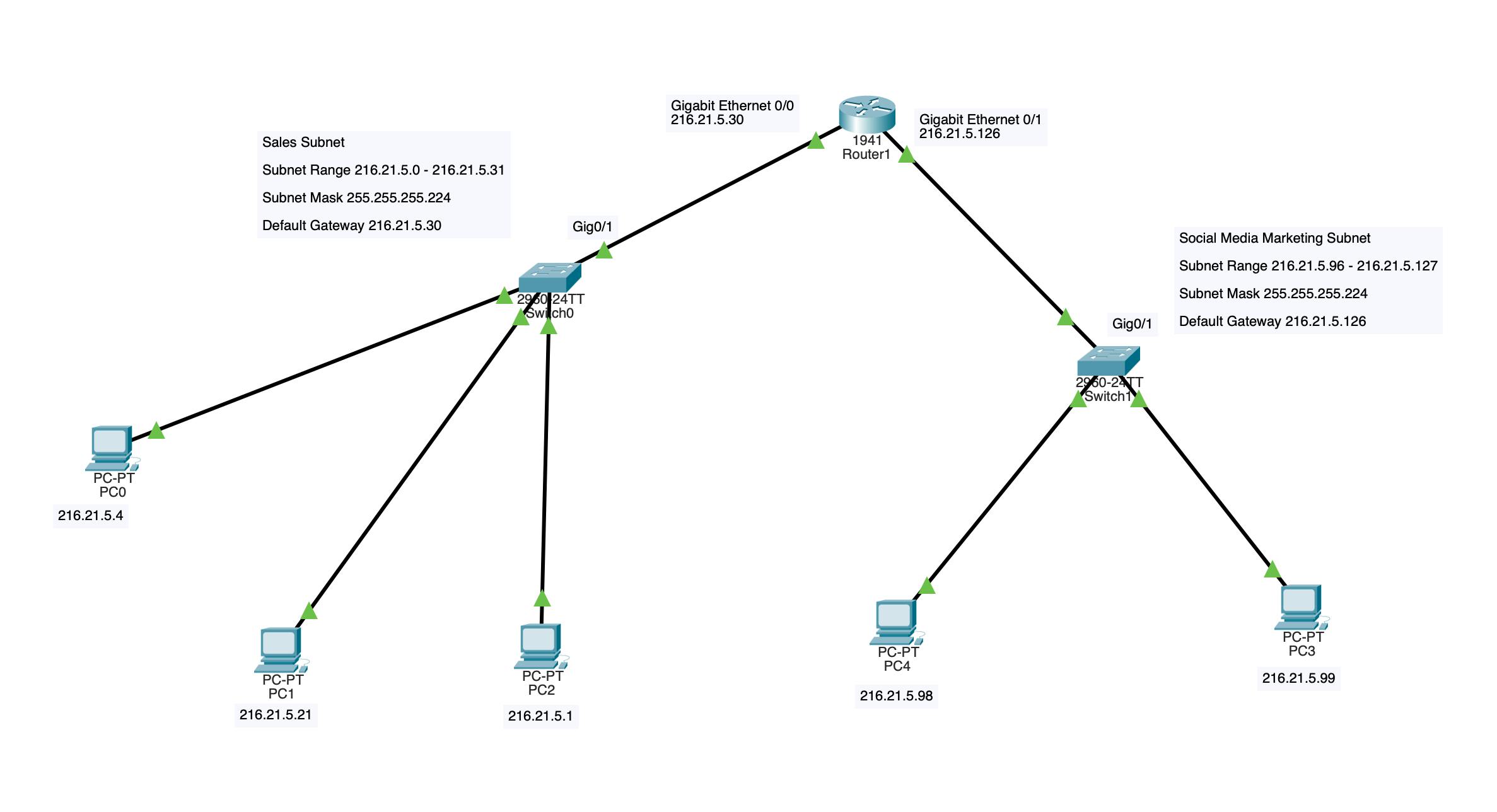
The image below shows the overall network with the router present. The router has two Gigabit Ethernet interfaces, GigabitEthernet0/0 & GigabitEthernet0/1. Similarly, one switch contains 24 ethernet ports and two Gigabit Ethernet ports, GigabitEthernet0/1 & GigabitEthernet0/2. You need to connect the Gigabit Ethernet interfaces on both the Router and Switch to each other. So one router interface for one switch's interface. The image below shows the network with the Router newly introduced, and it's available ports exposed.

The image below shows the connection process of connecting a switch to a router.
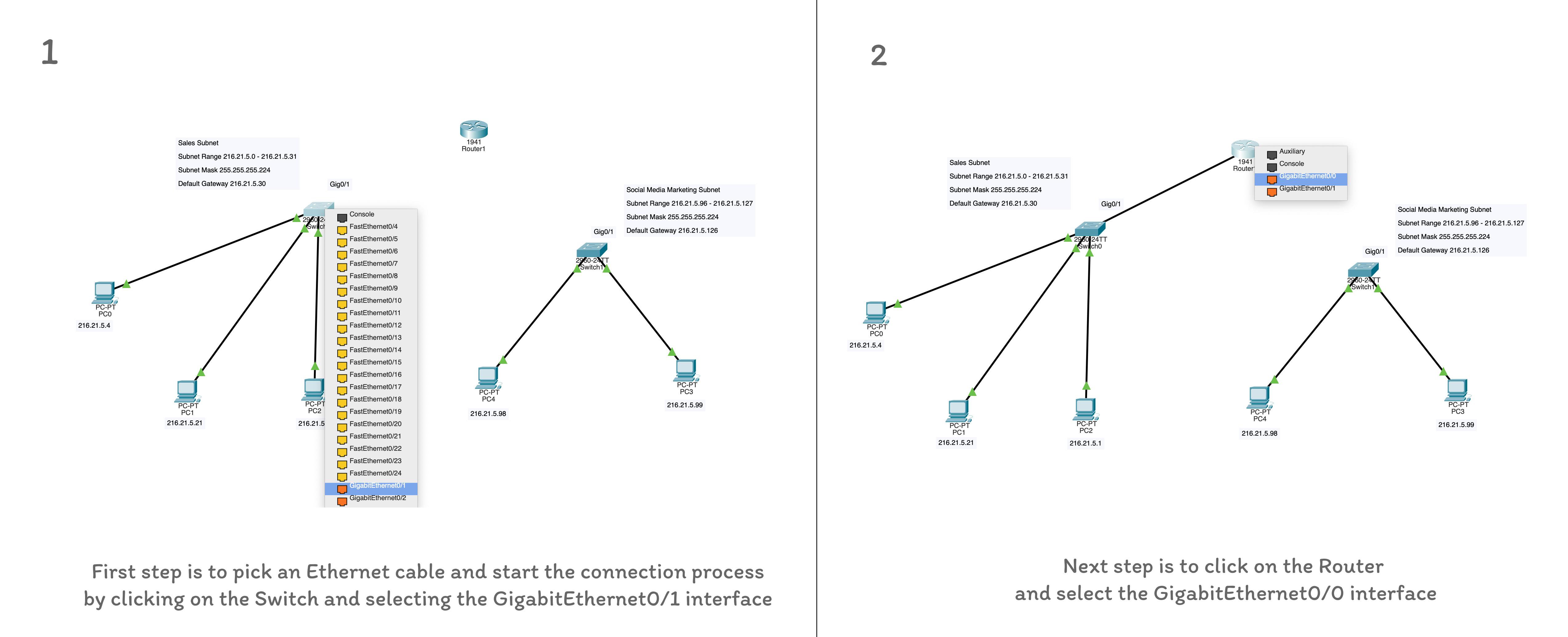
After connecting the interfaces, you should turn on the interfaces on the Config screen. On the same screen, you would set the default gateway address and the for the concerned subnet. So the sales GigabitEthernet interface is assigned an IP address same as the default gateway IP address of the sales subnet and and vice-versa for the GigabitEthernet interface of the marketing subnet. The subnet mask should be the same for the overall network.

With the router's connection complete and interfaces configured, you can have the interfaces labeled and the network complete.
Testing inter-network Communication
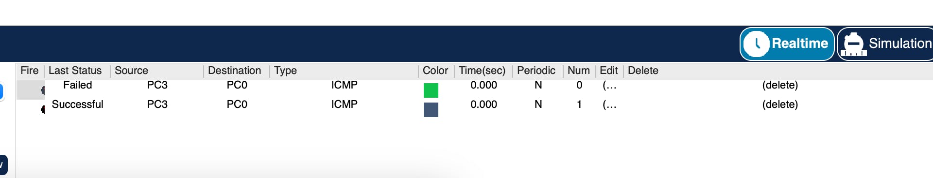
You can test inter-network communication by sending a ping (packet) using the Internet Control Messaging Protocol (ICMP) protocol from PC3 to PC0. If communication is possible, the packet will be sent successfully, else it fails. Due to initial network initialization, the first packet sent across a subnet fails. The reason the first ping usually fails is that the remote router in that LAN has to put the ping request on hold to send out an ARP broadcast to learn the MAC address of the remote device, then wait for a response, and then send the first ping through. This delay is usually too long. That’s why the initial ping request from your PC times out and declares that the ping failed. The next one between the same computers usually succeeds. The image below shows how to access the packet tool.

From the image below, you can see the table of sent messages and how the packet from PC3 to PC0 fails initially before it eventually succeeds.
Conclusion
This article explored a simple networking situation where two subnets are connected using a Router. You learnt about the need for subnetting and how to connect computers using a switch, and then how to connect two switches to a router. You learnt about the subnet masking, IP addresses, and the default gateway. Most especially, you saw how communication can be established between two subnets and how to test this communication. Thank you for reading. Adios ✌️ 🧡.